How I built my breather - by Jason Rogers
 (Sorry about all the numbers here, but there are several different
versions of metric and imperial measures to use and I've tried to cover
them all... I've not used Pascals, as they seem to only be used in
Australia, and as a result, Australians have got used to everyone else's
measurements!)
(Sorry about all the numbers here, but there are several different
versions of metric and imperial measures to use and I've tried to cover
them all... I've not used Pascals, as they seem to only be used in
Australia, and as a result, Australians have got used to everyone else's
measurements!)
There are two reasons that I want a rebreather.
The first is that I've reached the practical limit of the amount of OC gas I'm able to carry. The last dive I did OC I carried two 18 litres, pumped to 270 bar, (4800 L each or 170 cuft each) plus two 11.15 litre 215 bar cylinders, (2400 litres, or 85 cuft each) plus an assortment of stage cylinders and such that I clipped off to the line. A total of 14 400 litres, or 500 cuft of gas, and my set weighed more than I do.
The second is the cost of helium. Retail helium here is around 7 cents (Ozzie) per litre of free gas. To fill my double 18 litre cylinders with 50 percent helium mix costs $340.00AUD ($240.00USD or 150 Stirling) That's my disposable income for about a month, and so I simply can't afford to dive gas OC
So that's the broad parameters, I want a smaller rig, and I want to conserve inert gas. Now to the details that defined what I had to build.
Minimum duration 10 hours. This gives me a reasonable margin for diving interesting sites in remote places.
Multiple gases. This allows me to make the most of gas switching to
accelerate deco, however since I decided on this, I've become less sure of
the benefits of gas switching.
Low pressure fills. I can't afford to buy a booster pump for oxygen or helium and even if I could afford it, I can't afford to pay to take the booster away with me by air. To get around this, I've got to have cylinders large enough to get proper durations, with very low pressure decant fills.
Hand tool construction. I can't afford tools such as lathes and milling machines. This rules out some types of materials and some types of construction.Low weight for air travel. I want to take the unit away on trips, and so I can't afford to (for example) build in stainless steel sheet, as one of my later vapourware breathers called for.Low cost materials. It's pretty self expiatory. If I can't afford to buy it, there's not much point in designing around it!Quick construction. I knew that I had to build it quickly, as I have trouble finishing long projects.Easily expandable. In line with the problem of needing to get it diving quickly, before I lost heart, I needed a unit which could be expanded in capability as I gained experience, and got a better idea of what I wanted and needed from a breather. Expansions that I'm either considering or intend to do on the current breather are:
Some considerations
 Sensor Package, to convert from SC to CC
Second Loop
Shut off mouthpiece
Sensor Package, to convert from SC to CC
Second Loop
Shut off mouthpiece
The design for this hasn't really gelled in my mind yet. I'm still
kicking around ideas, and so I won't put anything up here till I get
something a bit more concrete
Second Loop
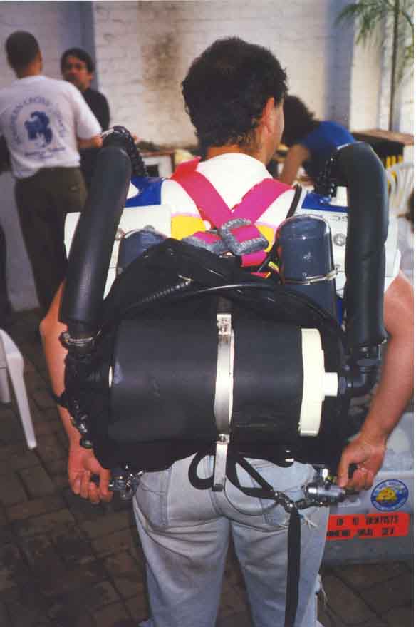
As you can see from the photos, I've chosen a horizontal scrubber layout.
This was for two reasons, the first was ease of construction and repacking
and the second was to provide room for a second back mounted scrubber,
without the breathing hoses getting tangled up in one another as would
happen with two vertical scrubbers.
I have to make some tests on the projected arrangement, but currently I'm
envisaging moving the existing scrubber up higher on my back, and placing
a similar unit in the same location that the current unit occupies.
Instead of using over the shoulder counterlungs for the second loop, I'm
intending to try a cummerbund style of counterlung, at about the same
level on the unit as the existing scrubber.
There are several problems associated with idle loops. Heating the loop,
and ensuring that the loop always contains a breathable mixture are
amongst them. On a cold water dive, kick starting the loop may not be
possible, but I'll have to have a shut off mouthpiece before I can start
trials anyway!
Shut off Mouthpiece
This is one of the items that I've found most difficult. Rodney's is a
work of art, and without any doubt, the best CC mouthpiece I've ever seen,
and probably the best ever built.
I've tried to replicate it in plastic, as I really don't like the idea of
using Aluminium with caustic alkalis anywhere present, but so far, I've
created a series of rather lovely, but quite useless leaky bits of plastic
pipe.
You're getting sick of this, but I'll update this when I've achieved
something!
Enclosure
You can see Rodney's enclosure in the photos. It works brilliantly well,
for the type of diving he's interested in doing. He can easily fit two 18
litre cylinders, one each side, or he can fit two 2 litre cylinders, what
ever he needs! The beauty of this is that the bailout and drive cylinders
are one in the same, and so he has a tiny, strong enclosure for just the
delicate parts of the breather.
On the other hand, I'm still trying to get the second loop idea to fly.
So I'll need a large, and light enclosure, that will provide mounts for
both sets of counterlungs, and contain the two scrubbers, and four small
cylinders that I'll need.
Currently, I'm thinking of finding a suitcase in ABS and removing the
locks and hinges, and replacing them with short rubber straps.
Counterlungs, and harnesses can mount on the "bottom" and the lid will
just fit over in a sort of clamshell type of way. So far I haven't gone
far with this idea. I've got to get the second loop going, so I'll have a
better idea of just what I am going to have to fit inside the enclosure.
No point in getting the enclosure right, and then finding that the stuff
won't fit!
Proper insulation
The current loop is more or less bare to the water. This reduces the
efficiency of the scrubber material, and promotes condensation of water
inside the loop. While there is a lower temperature in the loop, there is
a net movement of water out of the diver, and into the loop. Neither of
these are desirable.
The large flat counterlungs in my design are very difficult to insulate
effectively. I'm going to try gluing sheets of neoprene to the surface of
the counterlungs, but I don't expect this to make a great deal of
difference.
What I'm currently doing is gluing closed cell foam to the outside surface
of the scrubber. At the time of writing, the scrubber is about half
covered, and I'll update this when I get it completely covered and take it
for a paddle.
Active gas heating
This would really be the ideal solution to the problems of heat loss, and
loss of scrubber efficiency that result from very deep diving. I've not
got much further yet than the idea that I'd like to have active heating.
Problems I see so far are:
The Scrubber
In order to build something simple, and quick, I chose to use the good old
standby, PVC sewer pipe.
Easy to fashion, and easy to join, reasonably strong, and quite light,
with a wide range of fittings available off the shelf to make construction
easy.
I chose to make mine horizontal, for a variety of reasons, and this is how
I went about it.
I got 150 mm pipe, and cut it slightly shorter than the distance from one
shoulder to the other. This was to allow room for the end fittings, and
have it align with the shoulder counterlungs.
A 150 mm end cap was bought, and a hole made in the centre, to mount the
"through hull" fitting, (aka skin fitting). The through hull fitting had
the moulding ridges removed, and the hose barb cut off. Rubber gaskets
were made, and they went between the THF and the end cap. The gaskets had
a light smear of silicone sealant on them as well (silastic). The end cap
was then siliconed onto the pipe.
At the other end of the pipe, a screw on inspection cap was fitted, again
with silicone. This provides a way into the scrubber pack to change
absorbent.
The actual screw on cap received a similar treatment to the end cap.
Then another bit of 150mm tube was cut slightly shorter than the first,
and then slit lengthways. This was put over the whole lot, and glued to
the end cap and screw part of the inspection cap. This is because the
smell of the PVC glue takes years to dissipate, and the silicone glue that
was used in it's place is not strong enough.
The result was a tube with caps on both ends, one removable, and 1 1/4 BSP
parallel threaded tubes sticking out.
To this was fitted a 90 degree female elbow on both threaded tubes and
then I fitted a male hose barb on both elbows.
It's finished, and now must be packed.
A circular piece of coarse plastic mesh was cut out, so that it would just
fit inside the pipe. This had a perforated 100mm end cap cable tied to it
and it was dropped into the tube. Then a layer of open cell foam, and
another layer of plastic mesh. Then the absorbent material was put in,
and another layer of mesh, and then foam and then mesh-100mm-end-cap-assy.
The layer of absorbent is such that the endcap sits proud of the top of
the pipe, and the whole lot is compressed when the inspection cap is
screwed on.
The scrubber is shaken, and if there are any sounds of rattling material,
it needs more absorbent.
This ends up making a pretty large scrubber, with a smallish surface area
to insulate. The 90 degree bends increase the work of breathing, but you
have to turn the gas at some point, and it compares well with "there and
back" designs which force a single 180 degree turn on the gas.
150mm area is about the minimum I'd go for, but it's OK, due to the
effects of the twin counterlungs, which will be explained in that section!
The Counterlungs
Twin counterlungs, but why?
Twin counterlungs double the number of pulses of gas that flow through the
scrubber, and halve the gas speed.
Consider a single counter lung. It can be up or downstream of the
scrubber, but when you inhale, all the gas has to follow one path, and
when you exhale all the gas has to follow one path. In one of these
cases, that path will include the scrubber, and all the lungfull of gas
will have to pass though the scrubber, in half the breathing cycle.
Now consider twin counterlungs. Due to the hydrostatic pressures
involved, the level of gas in each lung will be very close to the same at
all times. Hence, when you exhale, half the gas goes directly into the
exhalation bag, and half into the inhalation bag via the scrubber. When
you inhale, half the gas that you inhale, comes direct from the inhalation
bag and half comes from the exhalation bag, via the scrubber.
This has some real advantages. The gas flow through the scrubber travels
at half the velocity, and so the energy used to drive it through is only
1/4 of the amount used if it went through in higher speed pulses. This
allows me to get away with things like 90 degree bends on the scrubber
pack.
Also the absorbent material is far more effective if it is given a bit of
time to work on the gas. With twin counterlungs, the gas gets to stay in
the scrubber for longer, and so you're not working the absorbent as hard,
and it lasts longer, and you have a lower CO2 level in the inhaled gas.
With a single counterlung, the full lungfull of gas passes through the
scrubber pack, and the absorbent only has the time while it's "passing
through" to work on it.
The actual material I chose is Layflat PVC hose, also known as "fire
hose". It is reasonably pliable but also very tough. It is designed to
have fittings put on it, and seal by compression, so closing the ends off
with clamps works very well. It's flat, and designed to roll up while
flat, and so it bends over the shoulder nicely. It's reinforced, and so
fittings such as drysuit inflator valves can be installed very easily.
It's rated "Food Grade" so it won't poison me.
The tee piece serves double duty. Mounted as you can see in the photos,
on top of the counterlung, it has inside a dividing wall, across the flow
of gas. This directs the gas into the counterlung, and there the water
separates from the gas, forming an effective water trap.
The left hand or exhalation bag has the O2 add valve, a drysuit inflator
valve, and the right hand bag has the over pressure dump valve (an
adjustable drysuit dump) and the auto diluent add valve, a scuba
regulator, that has been attached by a short length of corrugated BC hose
to a fitting from a BC. The exhaust port of the regulator has been
blocked up, and it's adjustable, to vary the level of gas in the bags.
This is not an ideal position for the valve, and the diaphragm has been
preloaded shut by putting a block of open cell foam under the diaphragm.
The Hoses
The breathing hoses come from a powered air purifier, from 3M, and the
hoses from the tees to the scrubber are third party replacement radiator
hoses. They're stiff, but they hold the counterlungs properly in place on
the shoulders. Not much to tell about the hoses really, but the 3M hoses
have to cure for a long time to rid them of the smell of plastiziser.
The Mouthpiece
This has to be changed on my unit (see the section on plans for the future
for more details)
The current mouthpiece is a remove-and-die unit, incorporating no shut off
system. The reason that I built my own, rather than using an old twin
hose one is that the old ones had very narrow bore, (around 19mm) which
made them unsuitable for the depths I'm planning on using the unit at, and
also the poor availability and high cost of spare parts for old twin hose
regulators. Nemrod in Spain is the only company making them now, and they
have no Australian distributor.
The actual mouthpiece is a 25mm female tee (25mm is the nominal bore as
stupidly described in the "metrification" of Australian plumbing supplies,
it's actually 1 inch BSPT which is about 1 1/4 inches) That has a couple
of exhalation valve carriers from Auer BA sets fibreglassed into the ports
of the tee, and a PVC pipe to thread adapter that has been heated and
squashed, screwed into
the middle port of the tee. It has a groove cut into it, and a scuba
mouthbit cabletied to it.
It works surprisingly well, i.e., it works, and that surprised me!
The hoses only just fit over the ports on each side, and are "rolled" on,
rather the way one puts on a condom, and then cable tied in place.
Diving Semiclosed
Till I get the sensor pack finished, and also during the testing phase of
the sensor pack, I'll be diving the set semiclosed. (Except of course for
the initial dives, which I did on CC O2)
These are the methods that I'm using. I've never seen this type
calculation mentioned anywhere, and of course, it's really quite untested.
If you're dumb enough to follow my lead, then you'll be doing the gene
pool a favour by dying, as you most probably shall.
I'm using two methods of calculating the lung dumps for semiclosed diving.
Note, I have NEVER measured the O2 levels in the set during a dive, so the
following is based purely on my speculations. If you do it, then do your
own speculations, and expect, as expected, to snuff it at any moment
during the course of diving the set.
The first method applies to shallow diving, where consumption of the O2 in
the loop will trigger addition of more diluent.
When diving this way, I calculate the MOD of the driving nitrox based on a
max PPO2 of 1.8 (This is higher than recommended by almost every agency in
the world) I then work out how much N2 will accumulate as I consume the
O2 at 3 litres/minute. (I'm currently quite unfit, and I don't' think my
VO2 comes anywhere near 3 litres/minute, if you are fit, then you need to
substitute a higher figure for this).
For example, diving with NTX 60. This is made up of 2 parts nitrogen, to
3 parts oxygen. If I consume 3 litres of O2 every minute, then I need to
dump 2 litres of "waste" nitrogen every minute. (In actual fact, one
needs to dump slightly higher than this if really consuming 3
litres/minute of O2, or else the "dump" would be pure N2, and the diver
would be dead)
My lung tidal volume is 3 litres, so on the surface, I would dump once
every minute.
At 3.3 metres, my lung's tidal volume is 4 litres absolute, and so if I
dump once every 2 minutes when below 3.3 metres, I'm dumping the 2
litres/minute that I need to.
At 10 metres, my lung tidal volume is now 6 litres absolute, so I need
only dump once every 4 minutes in order to dump the 2 litres/minute
At 17 metres, my lung tidal volume is now 8 litres absolute, so I need
only dump once every 5 minutes.
with SC diving, the diver needs to do a flush before ascending to
assure himself that there is sufficient O2 in the loop for the lower
pressure near the surface.
Still, even with flushing and mask clears and such, this is a very
efficient way to use drive gas. Since the flow is based on dumping,
rather than incoming gas, the amount of gas coming from the cylinder is
reduced if the workload isn't high.
To take the above example, if the diver is consuming 0.5 litres/minute of
O2 (typical rates for a diver at rest) then he is dumping 2 litres/min,
and consuming 0.5 litres/min for a total of 2.5 litres/minute that will
come from the diluent cylinder.
Oxygen levels can be worked out by looking at how much nitrogen comes in
and how much gas is dumped. In this case, the quantity of N2 is 2.5 X 0.4
or 1 litre. Since one litre of N2 comes in, and two litres are dumped,
the other one litre is O2, or in other words, the loop FO2 is 0.5
If he's working hard, and consuming 2.5 litres/min of O2, and dumping 2
litres, then 4.5 litres will be drawn from the diluent cylinder.
To work out the dump gas (and so the loop gas) FO2; 4.5 X 0.4 gives 1.8
with the remainder being 0.2 litres of O2 or 10% Fine if at depth, but
you can see the need for a flushthrough to raise the loop FO2 up closer to
the drive gas if working hard.
you employ this system, you need to work out your lung tidal volume,
and your own max VO2 and add in a margin for oxygen that goes out with the
dump gas.
Remember that the more you dump, the safer you are from hypoxia.
In a practical diving situation, working hard, I increase the amount of
dumping, it's still very little gas. Also, I tend to switch from one "per
minute" rate to another slightly deeper than calculated.
is compares with systems that add through a metered dosage system. They
must assume that the diver is working flat out all the time, and usually
add enough gas so that a diver consuming 3 litres/min of gas will still
have more than 20% O2 in the loop at all times.
So it's (Block of gas added each minute) - 3 litres of O2 equals (a gas
with more than 20% O2 left in it)
For 60% oxygen drive gas, that's the final gas supply having the original
40% of N2, unchanged, and 10% O2 left unconsumed, (40% + 10% = 50%, and
this 50% refers to the percentage of gas left over each minute after the 3
litres of O2 have been taken out. "10%" in this case, means 20% of the
remaining gas)
the remaining gas is 50%, this lets us know that the three litres of O2
consumed is equal to 100% - 50% or (also, but only in this case) 50%
Since 3L = 50%, we can say that 100% = 6 litres, and that's how much drive
gas must be added in a normal semiclosed system.
in a dumping system, the flow from the cylinder varies between about
2.5 litres/minute to about 6 litres, depending on workload, and in a
dosage system, the flow is constantly 6 litres/minute.
That's all a little garbled, (so sue me!) If you want to get it really
right, and a bit neater, do the Atlantis course, as that should teach you
about calculating flows for different mixtures on a dosage unit. Or
alternatively, sit down with a paper and pen and draw little blocks of gas
that look like this:
|______________80% N2________|__20% O2___|______3L O2___|
|______________40% N2________|_____________60% O2_______|
It's a much easier way of visualising what's going on than the forgoing
mess!
The second way of dumping gas is used when deeper than the point where
consumption of the O2 in the loop will reliably trigger the addition of
gas from the diluent cylinder. This seems to be something like 30 metres.
It works like this,
My tidal volume is around 3 litres.
If I dump 3 litres from the loop, and the drive gas gives a PPO2 of 1.6 at
the depth I'm diving, then 1.6 X 3 litres of O2 will enter the loop to
replace the gas I've just dumped.
If I do this dump once per minute, and at the same time, I'm consuming 3
litres per minute of oxygen, then you could say that I've taken one lot of
3 from 1.6 lots of 3, giving me 0.6 remaining.
In other words, the PPO2 of the gas will fall from 1.6 to 0.6 if I consume
3 litres of Oxygen from the 3 litres of gas.
u'll need to check how your tidal volume compares with your O2
consumption rate. I know people with a 6 litre tidal volume, and they
could dump once every two minutes.
Still, for me it's easy, and it beats counting breaths!
u'll also need to remember that if the PPO2 of your drive gas is lower
than 1.2, then you're going to be taking too much O2 out to support life,
unless you start increasing your dumpage rate.
Let me just reiterate the warning at the top of this page.
This stuff is untested, I'm trying it out to see how it goes, and I may
well die doing so. Even if it doesn't kill me, it may kill you, because
your breather, lungs and O2 consumption rates will be different to mine.
Back to top
Click here to go
Enclosure in a case
Proper Insulation
Active gas heating
The Scrubber
Counterlungs
Hoses
Mouthpiece
Diving Semiclosed
Sensor PackageAsk the A.A.R.G.

 Back to Main Page