A.A.R.G. Journal No. 5
February 1999

Editors Message
Well this issue has seemed like it’s taken forever to get together but here it is. We have a number of interesting articles by Jason Rogers, the continuation of our series on the Electrolung rebreather, a report on the Halcyon rebreather by Rod Nairne and some information on sensors from Bernhard Engl. In general, the world of rebreathers seems to be growing especially with the release of the Drager Ray and the number of sales of the Inspiration. We also get contacted regularly through the AARG website and by word of mouth by other homebuilders. In the past two weeks I have been talking to one of Australia’s leading wreck divers/discoverers, and a diver whith only ten O/W divers under his belt. Both these divers have homebuilts well under construction. With such a large number of rebreathers out there now it is important to keep the information flowing. Hopefully through understanding of how their units work, both homebuilt and commercial, divers will be able to increase their safety. It is with this aim that we continue to compile this journal which represents only a small, though vital, part of the information available to better understanding of rebreathers. safe diving, Scott Leimroth
HALCYON SEMI-CLOSED OPERATING PRINCIPLE
© Rod Nairne 1999Halcyon Manufacturing set out in the mid 1990s to develop and refine a rebreather system appropriate for the demands of exploring the depths and distances of the underwater cave systems of Wakulla Springs and the Woodville Karst Plain. Halcyon's goal was to produce a rebreather that was more efficient than conventional semi closed units, but with safety and task loading levels more in line with open circuit SCUBA. Although a maximum gas efficiency was a primary design criteria, Halcyon rejected the idea of developing a closed circuit rebreather (CCR) due to unacceptable task loading, potential for diver error, and lack of intuitive alarm systems. Diver safety would not be sacrificed for the last small fraction of gas savings. Halcyon’s design resulted in a semi-closed circuit rebreather that approaches the efficiency of a closed-circuit unit but offers none of the CCR’s complications. It is capable 2 hours of operation at 300 feet on a single 80cf aluminum cylinder. Between 60 and 200 feet, the Halcyon is 5 to 8 times as efficient as open circuit.
HOW IT WORKS
Unique among available rebreather designs, Halcyon's control system uses the physiological ratio between respiratory rate (RMV) and oxygen metabolism (VO2) to set the flow rate necessary for semi-closed operation. Workrate, respiratory rate, and metabolic rates are linearly linked. Of each breath on the surface, 4% of the total gas inhaled is metabolized, which works out to a 26:1 volumetric ratio. The diver's metabolic oxygen requirements are not affected by depth, therefore the volumetric ratio changes in direct proportion to increase in pressure/depth, which is why the Halcyon utilizes a variable ratio. When the diver exhales into the bellows, both the inner and main bellows fill. The volume ratio of the inner to outer bellows sets the vent ratio, which in turn was determined by the 26:1 physiological ratio. When the diver inhales, the inner bellows vents its contents to the water. Fresh gas is injected through redundant regulators to replace the vented gas on each breath.INTUITIVE ALARMS
The unique inner bellows also provides another distinct safety advantage. If the regulators stop adding gas for any reason, the inner bellows will continue to vent gas on each breath until the diver can't take a normal breath. This intuitive alarm is the same as felt with open circuit equipment, and the diver simply commences breathing from an alternate gas source. By contrast, with conventional semi-closed rebreathers such as the Drager Atlantis, the diver has little chance of recognizing that the gas flow orifice is partially blocked during a dive. The result can be fatal: oxygen will be depleted from the breathing gas until the onset of hypoxia. The hypoxic diver will still be able to take a normal breath, but the percentage of oxygen in the mix will continue to fall. Similarly, should the oxygen addition system fail on a closed circuit system, the diver has no reliable intuitive method of determining the failure. The diver in this case is dependant on the electronic warnings systems, which often fail at the same time as the oxygen addition system. Even when all alarms are functional, many experienced, competent divers have still become hypoxic due to "diver error," which really means equipment-induced error due to lack of intuitive alarms.EVEN MORE EFFICIENT: VARIABLE RATIO
At depth, the inner bellows of the Halcyon is mechanically squeezed by 2 levers, partially compensating for the change in pressure and maximizing gas efficiency. The venting ratio varies between 4:1 on the surface and 10:1 at 300 feet. This variance allows the Halcyon to be efficient for diving to any depth, both at the bottom depth and on deco, using the same Nitrox and Trimix gases that would be used on open circuit. Open circuit, closed circuit, and the Halcyon rebreather provide a relatively constant gas mix independent of diver workload. Significantly, fixed orifice conventional rebreathers such as the Drager Dolphin increase the inert gas percentage delivered to the diver during elevated workloads, resulting in a longer decompression obligation. The Halcyon is different: If the diver works harder, his RMV will increase, and the Halcyon will vent more gas proportionate to the diver’s increase in metabolic need. The Halcyon compensates for diver work rate and maintains a decompression advantage over conventional semi-closed units.WORK OF BREATHING:
The Halcyon utilizes a counterweighted bellows counterlung. The counterweight eliminates the negative inhalation pressure normally associated with back mounted counterlungs, such as on the MK15/16 military rebreathers. In fact, the counterweighted bellows configuration has outperformed all other types in US Navy work of breathing tests. Recent testing by the US Naval Academy demonstrated that the Halcyon exceeded the US Navy requirements for Resistive Breathing Effort (RBE) by 37% at an RMV of 62.5 lpm.Halcyon has engineered the optimal trade off between diver safety and gas efficiency in rebreather design. Its ease of operation allows the diver to concentrate on the dive rather than the equipment, and is the optimal choice for those divers needing to concentrate on an underwater activity without incurring significant task loading from their equipment. The Halcyon rebreather has already proven that it has the “right stuff” for the demanding work of underwater cave exploration; now the rest of the technical, scientific, and exploration diving community are discovering the benefits of an efficient, simple, and safe rebreather.
Passive Addition Rebreathers
© Jason RogersWe’ve all looked at one time or another at the equations that govern the movement of gases through active addition SCRs. They should now be well understood. There seems however, to be much confusion with respect to passive addition SCRs. There are two main types of passive addition SCRs around, and they all share some common aspects.
- Manual units
- Automatic units
Manual units are those in which the diver dumps a volume of gas out of the loop and replaces it. This volume may be a full lung volume, or a part of the loop volume, or some type of flush through. A description of a dive using a unit like this can be found on the AARG website, the dive report of the DeeWhy and Meggol.
Automatic units dump some part of the loop volume with each breath. Generally some specific fraction of the diver’s tidal volume. Automatic units can be further divided into three general categories.
- Fixed Ratio
- Depth Compensating
- Partially depth compensating
These dump a set percentage of the divers tidal volume overboard (usually from 10-25%) with every breath. Oxygen fraction varies with depth, becoming closer to the drive gas as the diver descends and the effective dump becomes greater.
Depth compensating.
These dump a percentage of the diver’s tidal volume, which varies in inverse proportion to the absolute pressure. On the surface these units generally dump between 20 and 33% of each breath, but that decreases with depth, to keep the Oxygen fraction constant and reduce gas wastage. The fraction dumped falls so that for instance a unit that dumps 33% of each breath at the surface, dumps 3.3% of each breath at 90m (10 Bar absolute). These units will provide a fixed FO2 regardless of depth, when used with the same drive gas because the effective dump remains constant.
Partially depth compensating.
These units are half way between the fixed ratio units, and the depth compensating units. They provide a high dump ratio near the surface, again 20-33% but the dump ratio is not fixed either with relation to a surface equivalent breath, or an actual breath at depth. They usually dump between 75% and 200% of a surface equivalent breath at 10 bar absolute, but of course this varies with design, and sometimes varies from individual unit to unit within one design.
Exactly how this dumpage is achieved varies from unit to unit, but some underlying principals can be discerned.
The factors which determine the composition of the inspired gas are, the Oxygen fraction of the drive gas, the oxygen consumption of the diver and the quantity of gas that is dumped from the loop. Generally it is taken that the composition of the inspired gas is equal to the composition of the dumped gas. This is not always so, as some designs inject the makeup gas (make up gas is the drive gas, injected into the loop to “make up” for the gas that has been dumped or metabolised) just upstream from the diver. Hence the dumped gas, is equal not to the diver’s inspired gas, but rather is equal to the gas that the diver exhales. However, it is bad practice to choose one’s gas limits based on the minimum level of oxygen found in the exhaled gas, as there is no guarantee that fresh gas will be injected on every breathing cycle.
The dumped gas’s composition is critical when it reaches the point where the O2 level is at it’s lowest. This point can be determined by calculation.
The dump gas can be divided into two major components, the inert gas that is “left over” from the metabolism of oxygen by the diver, and an amount of drive gas that has passed through the system, unconsumed. This second component can be thought of as an unavoidable wastage. It’s the part of the dump gas that contains the oxygen that keeps the loop above the minimum O2 level.
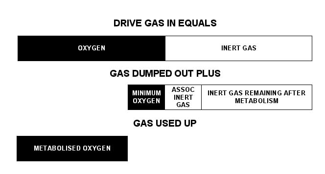
At this point, the only difference between the two types of rebreathers emerges. A manual system is calculated based on a time interval between dumps. This is based on the volume of Oxygen metabolised per unit time (VO2), or in other words, a rate of Oxygen metabolism. An automatic system is calculated with respect to individual breathing cycles, and depends on the ratio of tidal volume to the oxygen metabolised. Hence the convenient units are Litres and Tidal Volume Fraction, respectively.
So a couple of examples,
First for a manual system.
The drive gas is 50% O2, and the minimum dump gas O2 percentage is 20%. This allows the diver to surface at any time, and still have a breathable mixture. The O2 consumption is considered to be 3 litres per minute, which is normally a maximal VO2.
Now, the dump gas can be divided into two parts, for ease of analysis. One is the wasted gas. That’s the O2 and it’s associated inert gas that must never be removed from the loop gas. 20% of the dump gas must be Oxygen, and given that the drive gas is 50/50 mix, the inert gas associated with that will be the same volume, at 20%. Hence, adding those together, the wasted gas must represent 40% of the dump gas. The other 60% of the dump gas must then be the remaining inert gas that is left over after metabolism of the oxygen. If the diver is metabolising 3 litres/minute, then given that the drive gas is a 50/50 mix, the inert gas volume associated with 3 litres of Oxygen is also 3 litres. (Can you see why I picked 50 mix as the drive gas?). Now we can see that 3 litres is 60% of the total volume that must be dumped per minute.
- ?/3 =100/60
- Multiplying both sides by 3
- ? = 3X(100/60)
- ? = 300/60
- Dump volume equals 5.
or in other words, 5 litres of gas must be dumped from the loop per minute to keep the FO2 above 20%
I happen to have a tidal volume of 3 litres, so when diving 50% mix, I must dump twice per minute at the surface, and at 5/3rds of a bar (7m) I can dump once per minute. At 10/3rds of a bar (24m) I can dump once every other minute. This particular depth is rather awkwardly deeper than I’m really supposed to go on 50 mix, and in real life I usually use 60 mix and switch to a different drive gas below 18 metres. I also combine these procedures with the normal SCR safe practices such as a flush-through prior to commencing ascent and use of non narcotic mixtures.
In an automatic system the calculations are based on the fraction of each tidal cycle that is metabolised by the diver. There is a manufacturer at the moment who promotes a 26 to 1 ratio between tidal volume and volume metabolised. This equates to an Oxygen consumption of 3.85% of a tidal volume and is a normal human consumption rate. Divers however are notorious for maintaining exceptionally low ventilation rates, even with high workloads. You may be well advised to measure your own exhaled gas and compare the expired O2 level with inspired O2 level. I’ve done this experiment on myself, and found a worst case figure of a 10% difference. This was at the very end of an exhalation, and I would use 8% as my own worst case. My own open circuit gas consumption figures are not good however, and if you’re a gas miser, you may wish to use a more conservative figure.
Calculations proceed in a similar manner to the manual system, except that we’re not trying to find a litres per minute figure, but rather a fraction of tidal volume.
Using a 50/50 mix again, we can say that we will consume 0.08 of a tidal volume of oxygen, and the volume of inert gas associated with this will be the same (because of the fact that the drive gas has the same amount of oxygen and inert gas). Hence each dump must contain 0.08 of a tidal volume of inert gas. Again, we’ll look at a minimum FO2 of 20%, so the dump gas must contain 20% Oxygen, and it’s associated inert gas, another 20%. So 40% of the dump gas is wasted flushing gas. If 40% is flushing gas, then the other 60% gas must be the inert gas remaining after metabolism. You can arrange the figures in a similar way to the preceding calculation; 100/60 = ?/0.08 or multiplying both sides by 0.08 gives; 8/60 This is the fraction of each tidal volume that must be dumped overboard with each breathing cycle. To find the ratio of tidal to dumping, which is how these things are usually expressed, take the reciprocal, which is 60/8, or 7.5 to 1.
So for a 50/50 mixture, used from the surface, with a minimum FO2 of 20%, the minimum dump ratio is 7.5 to 1.
Now a fixed ratio rebreather will have the FO2 climb as the diver descends because the absolute amount of Oxygen metabolised remains constant while the quantity of gas that moves through the divers lungs and rebreather increases in proportion to absolute pressure. It is easy to calculate gas consumption ahead of time, simply calculate as for an OC dive, and divide by the dump ratio. Careful observers will note that this doesn’t include the metabolised O2. A very rough correction for the diver’s RMV can be made by adding the metabolised O2 to the dump volume, and recalculating the effective usage ratio. In the example above, the O2 consumption was 0.08. 0.08 plus 8/60 is 0.2133 and the reciprocal is 4.6875 at the surface. When the diver goes deeper, the oxygen consumption doesn’t change with depth, so the advantage over OC increases. As the depth increases the advantage tends toward the dump ratio, but never quite reaches it. So for an automatic dumper, using 50/50 drive gas, the advantage over open circuit is between about four and seven times better.
A depth compensating rebreather will use the same gas at depth as it does on the surface, and the FO2 will remain constant. To calculate gas consumption, do the same thing, but there’s no need to consider depth when calculating duration. The set will give an advantage over OC that is constant, and as though the diver remained at the surface. In this example the set would use the divers RMV divided by 4.6875 per minute. Of course none of this takes into account loop flushing and suit inflation, not insignificant factors with very small cylinders.
A partially depth compensating rebreather will fall part way between these two. Calculating gas consumption ahead of time is virtually impossible unless you know the exact dump ratio throughout the unit’s operating range. Unfortunately construction of a truly depth compensating rebreather has proven a formidable challenge, and from the figures that get bandied about, the units which claim full depth compensation are in fact at best, partially compensated. The key to picking this out is claims that the unit will come closer to the drive gas FO2 as depth increases. This is of course counter productive for a single gas system, however, it has safety advantages, allowing a lower FO2 drive gas to be used at great depth.
In all, it can be seen that gas dumping rebreathers can offer many advantages over OC, SCR and CC units, however, they, like all units, have drawbacks as well. Like everything else, these units are not majic carpet rides and a good grasp of what is happening inside your unit is essential, both during the design phase and during the actual operation of the unit.
SOME THOUGHTS ON SENSORS.
© Bernhard Engl 1999 (from a posting to the rebreather list by Walter Stark)
Recently the issue of sensor testing and sensor storage came up on the list, and most of it is wrong or misleading. Some hints to get things right:
- 1. Galvanic cell type sensors come in a sealed container. As soon as you open it, they come to life (some don't). It takes a while for them to stabilize (=reliable readings).
- 2. Galvanic cell type sensors die for five main reasons:
a) The electrode material gets consumed by the electrochemical process = normal end of life.
b) The electrolyte dries out.
c)The sensor gets poisoned: some contaminant enters it and the electrodes get spoilt. They get covered by unwanted by - products forming parasitic layers on the electrodes. Most of the "dead on arrival" sensors from a) belong to this group (contaminated during manufacture). The remaining two are specific for hyperbaric environments:
d) The sealing system fails and the sensor leaks. Mainly applies to sensors with gas spaces in the electrolyte or with a pressure equalisation system not suited for hyperbarics, such as intentional gas bubbles inside.
e) Gas bubbles build up in the electrolyte (DCS of the sensor) and act to buffer the PPO2, or block parts of the electrode surface or the membrane, yielding false readings, and may lead to bizarre behaviour if the bubbles start moving. - 3. The temperature compensation of most sensors is not suited for rapid changes of temperature. Readings are only valid in complete temperature equilibrium, which almost never happens in RBs (lab or chamber experiments may be very misleading...)
- 4. Storage: Keep the sensors in humid air and accept they won't live forever. The humidity helps to keep them from drying out and the small current from the air helps to keep the electrodes clean - by consuming them, contaminants have less chance to build up their destructive layers. The sensors stay "trained" and give reliable readings instantly and not without the usual (and unstable) wakeup period.
- 5. Pot Testing: Have a computerized pressure pot which is able to do actual dive profiles automatically. Decompression as for a diver (faster would kill the diver, everything slower does not make any sense at all). Record pressure, temperature, sensor output. Have multiple sensors of the same type in the pot and compare. Do hundreds of profiles from shallow to deep over a few months. Have reasonable "surface intervals" for the sensors and observe what happens during those, too. Have some humidity in the pot and use stainless steel only. Analyze the data with tools like MATLAB and assume calibration before every simulated dive. Reject all sensors showing failures, gross errors, major changes in step response, growth of nonlinearity, strange behaviour in the surface interval, before reaching most of their rated lifetime (this requires recording of the total oxygen dose normalized to percent hours.)
- 6. Field Testing: Have a modified RB running on open circuit so you know what gas the sensors see. If they see fresh gas, you don't have humidity and much lower gas temperature, if you have them on the exhalation side, you have humidity (->condensation) and higher temperature. If you have them on exhalation side after a filled scrubber they even get hotter. O2 consumed by metabolism can be treated as being constant per individual. Record the data from your set of three sensors and analyze. Readings still valid ? Sensors still track with each other ? Reaction in thermoclines or when entering cold water from a warm place or vice versa ? Recovery from flooding ? Never attempt to use sensors on the real thing before you are absolutely sure they will do.
- 7. Maintenance: Note installation date on each sensor. After a third of the service lifetime (which is a fraction of the rated lifetime) replace the oldest one with a fresh one. This means you always have a mix of sensor ages (or even manufacturing runs) and this lessens the threat to run into a systematic problem occuring at about the same timeframe. With this scheme you don't waste more sensors than with replacing all three at the same time after a full lifetime. The replaced sensors still may be good for gas mixing before their full life is over.
- 8. The big gotcha Even if you have found sensors that appear to work for RB (the Teledynes and their ripoffs, hint, hint) the manufacturer might change their manufacturing process at any time and unless they are specified for RB (which they aren't) he will care a damn whether this engineering change kills you - you are abusing the product, so who cares. You might be better off if you use sensors which truly are specified and made for RB. Beware of the garage outfits, though.
- 9. A related problem (although not about sensors): It is nearly impossible to get electronic components specifiedfor use in life support equipment. Almost every component manufacturer has a so called "life support policy" in the data-books essentially saying they prohibit use of their products in life support systems unless you get a written approval by their CEO, which you most probably can't. The guy is no fool. This does not mean those "industrial" grade chips won't work in your RB, it's just another obstacle for those who want to sell rebreathers and get rich by doing so. You want to use cheaper "commercial grade" components ? They are basically those who still limp along and are good for disposable items such as electronic toys, TVs, etc., and can suffer from dramatic performance loss at marginal supply voltage or close to their rated temperature limits, so beware. I hope this post helps somewhat to avoid the ongoing repetition and duplication of common errors and mistakes as evidenced by some previous posts on sensors and sensor testing.
Modifying Rebreathers
© Jason Rogers 1999
Modification of rebreathers is one of those things that seems to be easy, and yet is almost insanely difficult. Rebreathers, perhaps more so than any other device made by man, operate as a synergistic whole. I know that sounds rather new-age, but it’s true. Every component has to work together to produce a dynamic state that ranges around a set of values that have been imposed by human metabolic needs.
Designing a rebreather, as anyone who has done so can tell you, is sort of like a juggling act. You need to keep dozens of influences in mind to keep all the balls flowing along. It’s not like most machines, where each component can be worked out in isolation, and then the parts combined to make the finished product.
Everyone who comes in contact with a rebreather becomes an instant expert. They all want to be rebreather designers, and they’re all convinced that a few modifications to whatever it is in front of them will be a vast improvement. Ask yourself when you are in the same position, whether or not you can improve on the original designer's decisions with the few seconds of thought that you’ve put into it. Perhaps you can. Technology marches on, and all designers know that any design can be improved. The designers all know that with just a few more weeks, they can make it better, but eventually the point comes where they have to stop designing and start building. You may be tempted to step in and correct the designer’s errors.
Tread cautiously. Even the simplest modifications, to what appear to be external systems, quite apart from the core of the rebreather can have devastating results. I’ve seen a modification where the harness of the set was replaced by a jacket style BC. A simple update, that would modernise the set. No more innocuous seeming modification could possibly have been made. The entire loop was left untouched. However, the attachment for the BC was in a different location to the attachment for the harness. It interfered very slightly with the operation of the over pressure relief valve. In normal operation this had absolutely no effect and it wasn’t picked up in tests, or during extensive use. However during an emergency buoyant ascent, with a viscous nitrox mixture, the reduction in flow through the valve caused a pressure buildup inside the loop that made the scrubber lid blow off. The original designer would have been aware of the maximum performance needed from that valve, and designed it to meet those requirements. The tiny interference was enough to mean the set would no longer perform as intended at the outer edge of the envelope.
Returning to the juggling analogy, modifying a rebreather is like taking over from another juggler in mid juggle. You need to have an intimate awareness of the location, and direction of every ball before you take over, or the whole plot can come crashing down. Unless you have an awareness of the thoughts of the original designer that are at least equal to his own, combined with a good deal of hindsight gathered since the release of the set, you’re just courting disaster.
Electrolung Design III -Gas Supply
© Walter Stark
Two, 9 cf, 2100 psi steel gas cylinders were used for O2 and inert gas. These were lightweight models FAA certified for use in aircraft. Initially we used chrome plating to protect them, later we went to teflon coating. Beckman liked the more military look and there was some concern over possible hydrogen embrittlement from the chroming process.
Standard, old style, "K" valves were used as cylinder valves. On the inert side a SCUBA regulator-type yoke was used to mount a high pressure 1/8" NPT needle valve operated by rotary action of a T-shaped handle. Inert gas was valved in manually directly from the tank as needed using this valve. In use it had a very smooth precise feel. Inert gas was valved into the plenum at the bottom of the absorbent canister so that some mixing would take place before it got to the sensors.
On the O2 side a piston type first stage of a U.S. Divers single hose regulator was used to reduce tank pressure to about 60 psi. This is somewhat lower than such first stages normally deliver and was achieved by using a weaker piston spring. The normal hose to the second stage was used to connect the O2 supply to the solenoid valve. The octopus port of the first stage was used to attach an O2 bypass valve. This was a spring action, lever activated low pressure valve and it was protected by an enclosure which required opening a spring closed cover to get at the valve. The manual bypass valved O2 directly into the sensor compartment so the result was immediately readable.
I will digress briefly on O2. In addition to the physiological risks recently discussed in some detail on the list there is also the danger of fire and explosion. Valves, regulators, fittings and any other equipment used for O2 have to be thoroughly degreased of any petroleum based lubricants. If lubrication is required, as for example with the o-ring seal of a regulator piston, non-combustible silicone based lubricants must be used. Be aware that even a fingerprint oily with suntan lotion can start an explosive fire with O2. Once an O2 fire starts all sorts of things you might not ordinarily think of as combustible burn ferociously. I have heard stories of chamber fires in which everything inside, including the occupants, was reduced to ash.
My partner Kanwisher was on one of the advisory panels to NASA in connection with the Apollo program. Although he recommended using a mixed gas atmosphere in the Apollo capsule he was over-ridden by the engineers who felt that monitoring the PPO2 was too difficult. John knew better as he had been doing it for several years in conjunction with his work on respiration but the engineers prevailed. The result was the fire which killed three astronauts.
The solenoid valve we used was a miniature 12 volt one made for pneumatic control. We equipped it with a miniature screw adjusted needle valve outlet. When the setpoint is reached and the solenoid is triggered it takes perhaps three or four seconds for the sensors to respond and rise enough to cut it off again. The solenoid needle valve was adjusted so that the O2 injected raised the PPO2 to a peak pulse of about 0.75 Atm and would usually trigger a couple of beeps from the audible alarm. Within a couple of breaths mixing brought the level back to perhaps 0.65 after which it dropped more slowly as it was consumed by metabolism until the setpoint was reached again after about a minute or so. That would be for moderate activity such as easy swimming. At complete rest it would of course take longer to drop back to the set point and less time if you were actively swimming.
If the needle valve was adjusted to a lower flow rate solenoid activation would be more frequent and of longer duration placing an unnecessary drain on the solenoid batteries. If much higher flow was adjusted for the O2 spikes would be too high and the alarm would be sounding much of the time. I think there are now smaller, more power efficient solenoid valves available.
The solenoid and manual bypass valves were of the downstream type so that if high pressure leakage from the regulator occured it would release when it reached the level where it overcame the spring tension which normally closed the valve. This is important to prevent either valve lockup or blowing out the supply hose in the event of a high pressure leak. In the event of O2 leakage from either valve the cylinder valve could be used to cut it off.
The gas cylinders were mounted on either side of the central larger cylinder containing the absorbent canister and electronics section. This assembly was worn as a back pack with the valves at the bottom at hip level. Inert gas had to be added several times on descent and at other times if you lost any from nasal exhalation. Manual O2 was normally only used in decompression. The inert gas valve was therefore on the divers left side leaving the right hand free for more complex tasks. Swapping sides for southpaws would have been easy but I don't recall anyone ever raising the question. It was no big thing either way.
Please Note
The A.A.R.G. is dedicated to the dissemination of information about rebreathers and rebreather diving, particularly in Australia and the South Pacific region. Our aim is to increase the general diving publics' awareness about rebreathers and related issues and to provide you with the stimulus to make your rebreather diving safer. However NO responsibility is taken for the accuracy of any information presented in this newsletter. You should always seek out verification of any information you acquire about rebreathers and use your own judgment as to it's validity to your context. Be safe, be conservative and dive safe. Remember, this is not diving equipment, this is life support equipment and your life may depend on it.
Ask the A.A.R.G.

Click here to go  Back to Main Page
by Scott Leimroth ©